

Sizing of a NORGLIDE® Bushing
Specification
Manufacturing tolerances, or variations, are an everyday occurrence for many of our customers. That is why Saint-Gobain engineers work hard to ensure our customer’s systems work consistently. The worst case scenario of tolerance stack-ups occur when a housing and a shaft are at equal and opposite extremes of their tolerance ranges – simply, the smallest inner diameter of the housing with the largest diameter of the shaft as one example. This can lead to excessive torque for a particular assembly whilst the other extreme, large housing diameter and small shaft diameter can lead to low or no torque.
In the case where a bearing is placed between the shaft and housing, the bushing inserted into the housing will have an inner diameter tolerance equal to that of the housing tolerance plus twice the bushing wall thickness tolerance. This can lead to a third element in the system adding to the tolerance stack up.
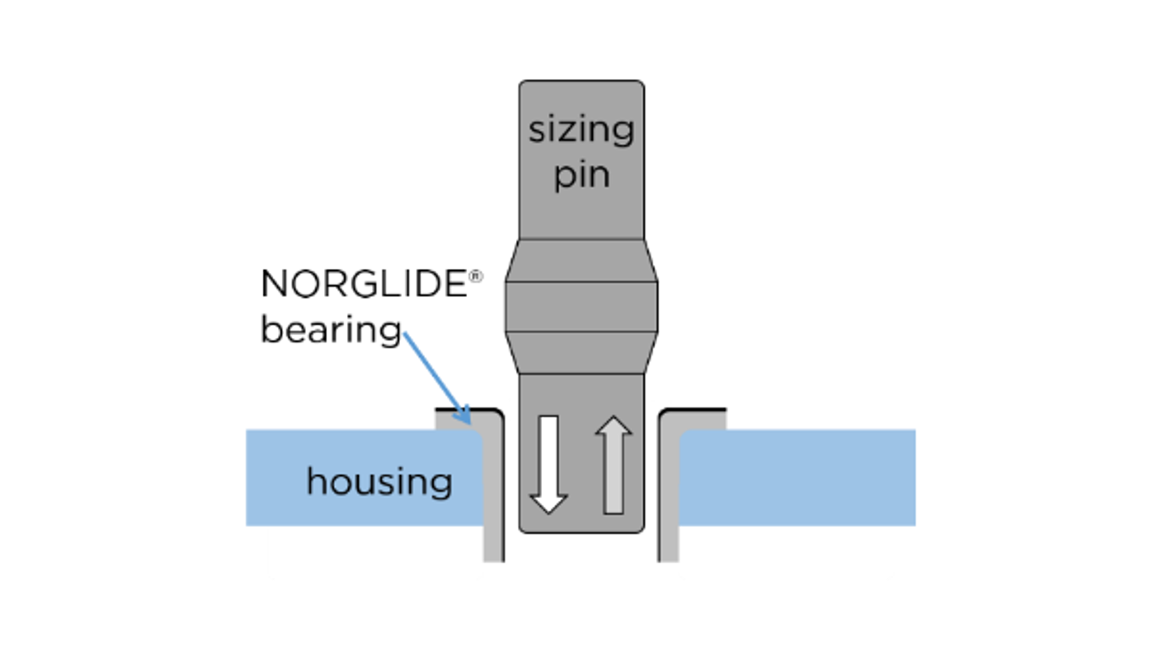
NORGLIDE® bearings, in combination with a sizing procedure can help to minimise this issue. Sizing, as shown in Figure 1, is a calibration of the inner diameter of the mounted bearing using a sizing pin of a controlled outer diameter to plastically deform the bearing material into a specific and significantly more consistent value. This leads to a more consistent inner diameter than even the housing alone.

Figure 1: Schematic representation of the sizing procedure. The sizing pin features an “olive” which has a larger outer diameter than the required inner diameter due to the elastic behaviour of the bearing's sliding layer. The pin is inserted into the bushing to plastically deform the PTFE sliding layer into the specified thickness. It is important for Saint-Gobain engineers to work closely with customers so we can ensure an effective sizing procedure is implemented.
This process will not be effective on all bearings, however. NORGLIDE® SM, SMALC, M and MP Bushings all incorporate a metal stretched mesh or metal fabric layer within the PTFE compound that helps the sizing process by allowing plastic deformation of this layer. Figure 2 shows the possible control of the inner diameter using increasing sizing pin diameters with NORGLIDE® SM Bushings. The level of sizing that is achievable depends on the total stiffness of the bushing material. It should be noted that due to the thickness of the deformable layer, there is a limit to the highest wall thickness reduction possible which is why it is important to work closely with our customers to ensure the initial problems are understood so an effective, custom-made solution can be provided.

Figure 2: An example case of wall thickness reduction after increasing sizing pin calibrations for NORGLIDE® SM Bushings of dimensions: thickness = 1 mm, length = 17 mm. inner diameter = 12 mm. The sizing steps were performed at 50 µm intervals. The width of the shaded area indicates the range in standard deviation from the average values.
Saint-Gobain Performance Polymer Solutions China
- No.1476 Kunyang road, Minhang district, Shanghai. 200245
- 400 888 0198
- sales.PPSCN@saint-gobain.com


Online Chat